Conductor
Copper and aluminum are the standard materials used for bus conductors. Aluminum has a conductivity of approximately 60 per cent of copper. The lower conductivity favours aluminum since the required larger dimensions give a higher section modulus and slightly lower skin effect.
Using aluminum conductors result in saving approximately one third the weight of conductor material for the same current-carrying capacity.
Round, square or octagonal aluminum conductors are used. Conductivity and dimensions are selected for each ampere rating to provide maximum current carrying capacity and mechanical strength. Maximum length of conductor consistent with the layout of the bus are used to keep the number of joints to a minimum.
Enclosure design – Insulated or bonded
There are three housing designs available. The conductor current that induces housing voltage in turn causes currents to flow in the housings. The current flow paths depend on the availability of closed circuits. The predominating circulating pattern is determined by housing interconnections.
On one arrangement, the housing sections are grounded at one end, and insulated at the opposite end, as shown below.
This arrangement has the purpose of preventing the circulation of currents between housing. This is called the “Discontinuous” or “Insulated-Housing Arrangement.” Gasketing is used to insulate the housings.
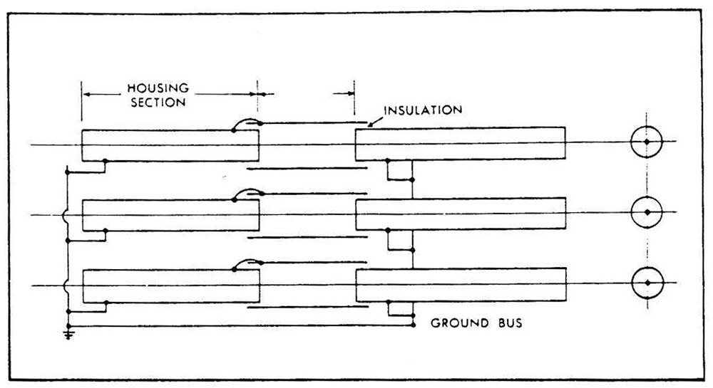
Discontinuous enclosure type bus.
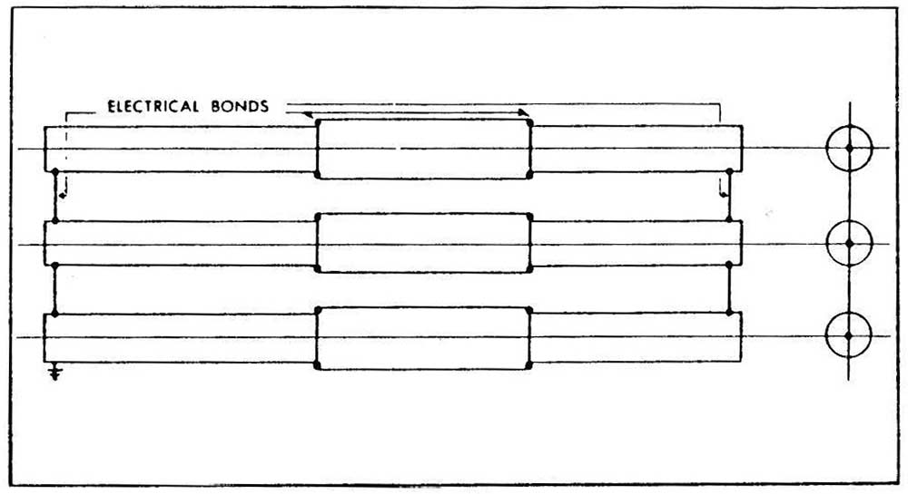
Bonded enclosure type bus.
Another arrangement consists of electronically bonding the housing together as illustrated. This arrangement has the purpose of permitting the free circulation of currents between housings. This is called the “Continuous” or “Bonded-Housing Arrangement.“ Bolted or welded cover seams are used to bond the housings.
The third design known as the “Discontinuous Bonded” arrangement combines the advantages of the first two and is as illustrated.
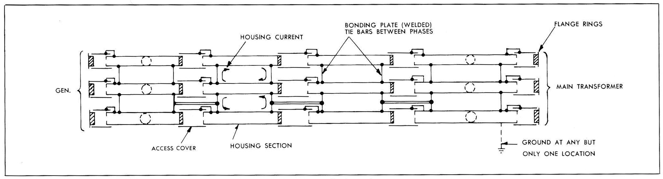
Discontinuous bonded enclosure type bus.
Forced-air cooled bus
On a high current rated bus, consideration should be given to forced-air cooling. On a forced-air cooling bus, a standard-design, self-cooled conductor approximately one-half the forced-cooled rating is used. (This presents savings both in space and the purchase price of the bus). The resultant heat generated by increased losses is carried away by cooling air in the closed system of an air-to-water heat exchanger. A self cooled bus to the highest rating is now often the preferred one because to its high cost of losses.
An economic study should be made to compare the increase in losses, versus the purchase price savings of using a smaller conductor. The value of losses is generally capitalized over the expected life of the equipment. The loss evaluation is usually stated in a flat rate capitalized value in dollars per kW of losses with the actual evaluation depending on the predicted efficiency of the station. Giving this flat-rate capitalized value to the bus manufacturer permits him to select an economically optimum conductor size. The power requirement of the blower fan should also be considered in system losses.
A source of cooling water is required for the heat exchanger. Station condensate water has been applied to this purpose.
Consideration should be given to operation desired in the event of loss of cooling air. Specifically, how much load must the bus carry, and how long under these conditions?
Without forced cooling, the bus is subject to overload based on its self-cooled rating. The temperature of the bus raised exponentially with time to an ultimate value where annealing begins. The time that a bus can be operated at full load without cooling air and without damaging effects can be predicted by the bus manufacturer.
Automatic devices should be included to give alarm signals in case of inadequate functioning of any part of the system.
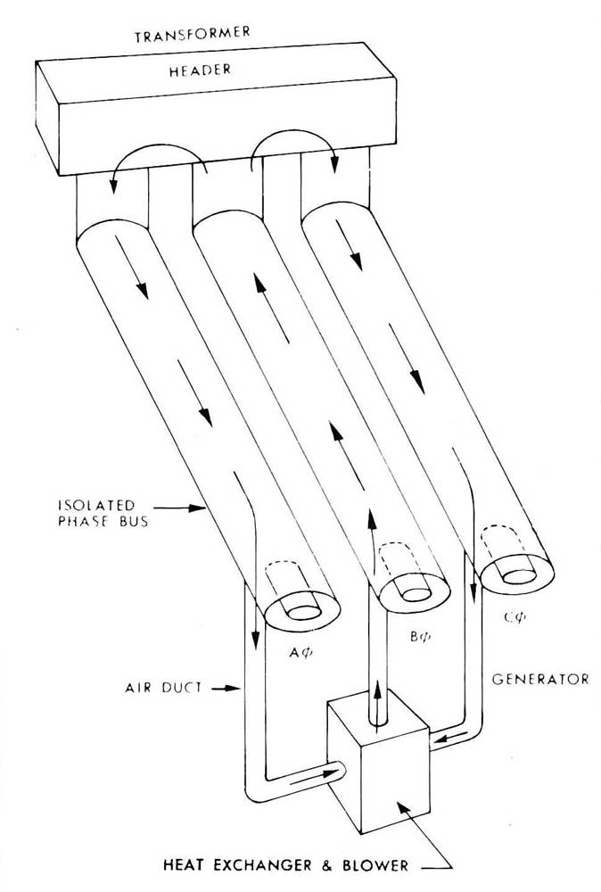
Air flow diagram forced-air cooling.
Connectors
Laminated aluminum connectors are used to compensate for the expansion and contraction of the conductor due to temperature changes. To facilitate the installation, one end of the laminated connector is factory welded to the conductor and the other end is field welded during installation.
Braided copper connectors are used for termination of the conductor at generator, transformers and associated equipment.
Porcelain or Molded Epoxy Resin Barriers
Barriers prevent interchanges of air at different temperatures, leakage of hydrogen or infiltration of dust into the bus. They are used when bus passes through exterior walls and the generator or other terminations.
Filter Drains
Filtered drains are provided to drain off any water that might accumulate due to condensation. They are constructed to prevent dust from entering the bus enclosure.
Welded laminated connectors.
Bus unit showing laminated connectors welded at one end to conductor
Single-phase bus showing a conductor ready to receive bolted laminated connectors.
Grounding of isolated phase bus
A continuous ground conductor should be provided in parallel with the isolated-phase bus to ensure that all enclosures are grounded. The ground bus may take the form of a separate conductor or it may be the enclosure itself, or it may be the supporting structure, if a continuous electrical path can be provided of the same momentary rating as the main-bus conductors. The ground bus shall be capable of carrying the rated momentary current of all the bus for a period of 2 seconds.
The ground conductor is preferably connected to the station ground at one point only, although more connection points are satisfactory if induced-current loops have been avoided. Induced voltages across insulated joints in the housing should be kept as low as possible and preferably below 2 volts during rated-current operation.
Adjacent and supporting structures
For high-current installations, consideration should be given to the problem of induced magnetic heating and induced circulating current in nearby metallic members such as support beams, reinforcing rods, etc. Suitable insulated gaps in the steel work to eliminate enclosed loops and arnortisseur bands around steel members, will aid in solving the problem.
It is recommended that the suggested procedure be followed to the extent that the ground currents in any adjacent metallic material be kept below 10% of the bus-phase currents or low enough so temperature rise is within the limits previously stated in Table regarding temperature limitations.
Use of the bonded-design housing limits stray residual magnetic fields such that special treatment of adjacent metallic material is not required.
Ventilation
Self-cooled metal-enclosed bus that have sections located both inside and outside a building, (so that ambient temperatures may be appreciably different) should include sealing means or baffles to prevent an interchange of air between the sections. Further more, widely fluctuating ambient air temperatures for any one section of bus necessitates consideration of the resulting enclosure air temperature, condensation, and pressure change. Some form of ventilation with filtered breathers or means of air circulation should be utilized and provided at the low point in vertical sections to prevent accumulation of condensation.
Terminations
Bus conductors are electrically attached to the generator or transformer bushings, or switch terminal pads.
The terminating equipment at the generator may require hydrogen seal-off bushings or baffles. Under these conditions, provisions for venting hydrogen leakage to the atmosphere are included
Switches or links for station-service transformers
A generator bus frequently has tap connections to station-service transformers through group-operated disconnected switches or disconnecting links. Switches should not be operated to close to an energized bus.
Links should be easily removable, but only when the bus is de-energized. Both switches and links shall be capable of carrying the rated momentary current in that section of bus.
Disconnect links can be supplied in the main leads but as the current rating gets higher, the task of removing links gets more difficult. Telescopic disconnect switches are recommended for this application.
Loss calculations
All conductors carry electric current will produce power losses. The enclosure, carry circulating currents will also produce losses. In making power-loss calculations, only the losses in the conductor and enclosure are considered. Currents induced in adjacent structural loops should be minimized to reduce their extraneous losses. These may be reduced or eliminated by making these loops electrically discontinuous, or by use of amortisseur grip to shield the loops. The bus manufacturer should be consulted for advice on this problem.
The calculations should be based on a temperature which includes a standard ambient value of 40 degrees C, plus the average temperature rise when the bus is carrying rated current.
If the bus is forced-air cooled, the total losses for the blower equipment shall be added to the power loss. Refer to IEEE/ANSI C37.23 for a complete treatise on isolated phase bus enclosure losses covering both the “continuous” and “ discontinuous” enclosure designs.
For ISO-Phase bus data regarding sizes and phase spacing, minimum clearance etc…For different bus rating, please consult the factory.